Poor Man's Air Box Mod
August 2008
(Speedy Note: Photography and text were submitted by website viewer Felix T Cat. Got an article you'd like to submit? Contact me for details.)
This document will cover the “Poor Man” intake mod for the 04-07 CBR1000RR. I will not go into removing the intake from the bike because that can be found in the Atech install How To section. Once the intake is removed follow this guide to dis-assemble / remove the divider plates and re-assemble the intake allowing for a much cleaner air flow. I personally picked up a “spare” intake on ebay so I could do this mod without having my bike down at the same time.
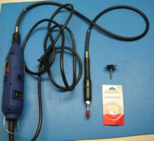
Tools used: Dremel w/ extension to make it easier to handle, re-enforced cut off wheel, cone shaped sanding bit.
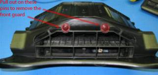
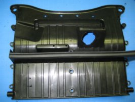
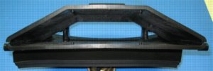
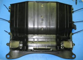
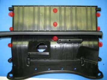
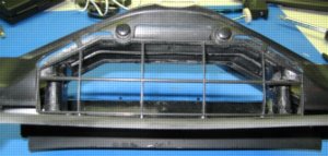
Here is a picture of the intake, stock before you begin. This is the view from the front of the bike:
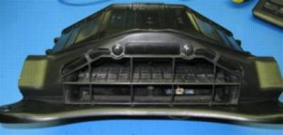
Step 1: Remove the front guard by pulling on the top two pins circled.
|
|
|
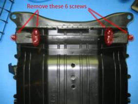
Step 2: Remove the flapper door cover by removing the 6 screws shown. Once done you will see the flapper plate.
|
|
|
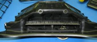
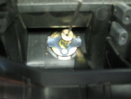
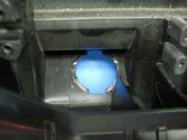
Step 3: Remove the flapper door by pulling out the metal bar on the back side:
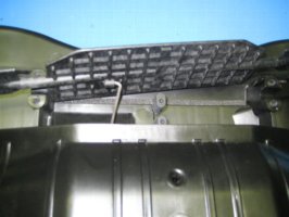
Step 4: Remove the vacuum module by slowly turning the assembly from the outside of the intake. You will need to turn it about a quarter of a turn to line up the tabs.
|
|
|
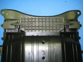
Step 5: In this step you need to cut off 9 heat stake pins. The picture shows them circled. I used a razor blade to cut off the rounded part and then a dremel to cut away a little of the pin. For the pin in the very center I had to use the dremel because I couldn’t get the razor blade in close enough.
Step 6: Once you have the heads cut off the pins very gently pull the
top and bottom apart.
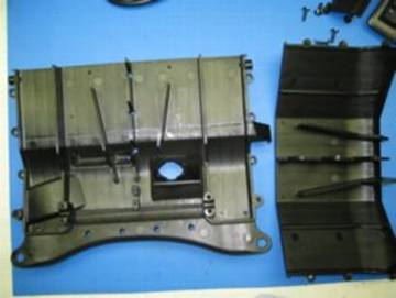
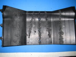
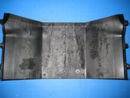
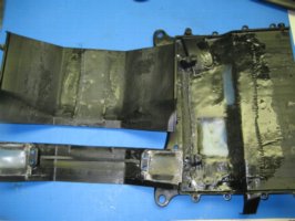
Step 7: From here on out it gets VERY messy so make sure you are working in an area you can clean up later. Now you want to start removing the fins from the top and bottom. I started with the top and used the dremel with a cutting disc to cut off the majority of the fin first and then a sanding disc to remove any remaining plastic.
|
|
|
|
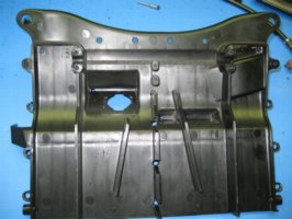
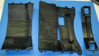
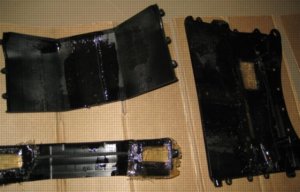
Step 8: Now do the same for the bottom. Since I was going to fiberglass the intake smooth I cut off the two large sections that hung down under the intake (one is for the vacuum module) as shown in the pictures below. I decided to leave the 4 screw mounts in the center for the flapper door lid to provide a little more strength to the finished assembly.
|
|
|
|
|
|
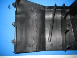
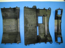
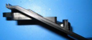
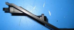
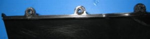
Step 9: SUGGESTION: Look at the next 2
pictures. They are of the flapper door holder pc. The section I
took out is not required but it will make it easier to lay the fiberglass if
you choose to use it later.
|
|
|
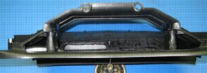
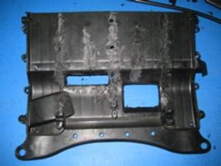
Finished the cutting, now onto the fiberglass. (NOTE: The vacuum module in the
pic is simply to prop up the intake, it is not installed)
|
|
|
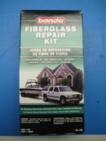
For the fiberglass I picked up this kit for $10 at my local wallmart in the auto repair section. Follow the directions on your kit, I will include pics of my process. FYI, this stuff stinks pretty bad.
Precut the pcs of fiberglass:
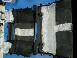
After mixing and laying on the resin. Once the resin dries I used the dremel to trim the fiberglass. I would suggest you wear breathing protection to keep from breathing in the dust.
|
|
|
Step 10: Reassemble the intake. I decided to drill small holes in the heat stake pins and use a small amount of caulk and zip ties to hold everything together.
|
|
|
NOTE: I initially was going to use the front guard (vs leaving the intake wide open) but when I put it back on I noticed it covers the small side intakes completely. Since the purpose was to open up the intake I decided not to re-install it.
Have questions, ask
Felix T Cat.
This page is part of a frame set. If you reached this page via a search engine please click here to go to the main page.