Honda 919
Tail Section Modification
Part 2: Turn Signal Integration
September 2002
After trimming my rear fender in
Honda 919 Tail
Section Modification Part 1: Fender Trimming I decided to take it one
step further and integrate my turn signals into the rear tail light/brake light
assembly. I did some research and found a couple of options on how to do
this. One was to spend $60.00 on the "Eliminator". The other was to
spend $12.00 on a trailer wiring harness. I decided to take the $12.00
route.
 The
tools you'll need are: A test light, wire cutters/strippers, various allen
wrenches, 8mm and 10mm sockets and socket wrench, zip ties, water proof butt
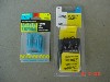
connectors, and electrical tape. If you really want it to look
professional have some 3/8" corrugated wire wrap on hand as well. Of
course you'll need the turn signal integrator unit. I picked mine up at
Advanced Auto for $11.99. The part number on the package is 48845.
It has three wires coming from one side, and 4 wires coming from the other.
The
tools you'll need are: A test light, wire cutters/strippers, various allen
wrenches, 8mm and 10mm sockets and socket wrench, zip ties, water proof butt
connectors, and electrical tape. If you really want it to look
professional have some 3/8" corrugated wire wrap on hand as well. Of
course you'll need the turn signal integrator unit. I picked mine up at
Advanced Auto for $11.99. The part number on the package is 48845.
It has three wires coming from one side, and 4 wires coming from the other.
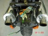
Remove the seat and tail section. To
remove the tail section you'll remove the 4 allen bolts that hold the grab rail
in place and remove the grab rail. Then remove the two 10mm bolts under
the seat on the rear of the tail section. These two 10mm bolts have small
rubber caps on them. Finally, remove the two plastic snaps on each side up
close to the engine. The tail section will then slide backwards and allow
you to reach in and unplug the rear tail light/brake light connections.
Set the tail section aside. I used a Sharpee marker to mark all electrical
connections so that I didn't get anything mixed up on re-assembly. So far,
the clear tail light/brake light connection is the left bulb, and the black tail
light/brake light connection is the right bulb.
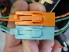
 Slide
the small clear wiring protector back and unplug the light blue, orange, and the
small clear connectors. The orange connector is the left turn signal, the
light blue connector is the right turn signal, and the smaller clear connector
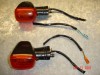
is the license plate lamp. Remove the two 10mm bolts that hold the turn
signals on the rear fender and slide the turn signals out and lay them aside.
Make sure the orange and blue connectors don't catch on part of the rear fender
as you slide the turn signals out. Finally, remove the two 8mm nuts and
the two allen bolts in the rear fender. The 8mm nuts are located on top of
the rear fender below where the brake light would be, and the allen bolts are
six to eight inches forward on the INSIDE of the rear fender. Now
the entire rear fender should come off. Remove the two phillips head
screws that hold the license plate lamp to the rear fender.
Slide
the small clear wiring protector back and unplug the light blue, orange, and the
small clear connectors. The orange connector is the left turn signal, the
light blue connector is the right turn signal, and the smaller clear connector
is the license plate lamp. Remove the two 10mm bolts that hold the turn
signals on the rear fender and slide the turn signals out and lay them aside.
Make sure the orange and blue connectors don't catch on part of the rear fender
as you slide the turn signals out. Finally, remove the two 8mm nuts and
the two allen bolts in the rear fender. The 8mm nuts are located on top of
the rear fender below where the brake light would be, and the allen bolts are
six to eight inches forward on the INSIDE of the rear fender. Now
the entire rear fender should come off. Remove the two phillips head
screws that hold the license plate lamp to the rear fender.
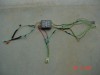
 Unplug
the final clear connector that goes to the rear tail light/brake light.
This will allow you to remove the tail light/brake light harness from the bike.
Remove the black plastic sheathing over the tail light/brake light wiring
harness. Cut the wiring coming from the turn signals about mid way and
remove about half of the remaining black plastic sheathing on the turn signal
pigtails. Go to a work bench or table with this wiring as well as the
48845 trailer wiring harness. You can trim the wires coming from the
wiring harness down to about six inches to make it easier to work with.
***NOTE: Honda splices off to make one connection become two in three
different places on the rear tail light/brake light wiring harness. These
three places are underneath the electrical tape on the
GREEN, GREEN with
YELLOW STRIPE, and
BROWN wires. This is how they get voltage to two lamps coming
from one harness connection.
Unplug
the final clear connector that goes to the rear tail light/brake light.
This will allow you to remove the tail light/brake light harness from the bike.
Remove the black plastic sheathing over the tail light/brake light wiring
harness. Cut the wiring coming from the turn signals about mid way and
remove about half of the remaining black plastic sheathing on the turn signal
pigtails. Go to a work bench or table with this wiring as well as the
48845 trailer wiring harness. You can trim the wires coming from the
wiring harness down to about six inches to make it easier to work with.
***NOTE: Honda splices off to make one connection become two in three
different places on the rear tail light/brake light wiring harness. These
three places are underneath the electrical tape on the
GREEN, GREEN with
YELLOW STRIPE, and
BROWN wires. This is how they get voltage to two lamps coming
from one harness connection.
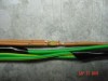
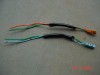
 !!!!---NOTE:
Honda made a mistake on the wiring of the turn signals. Coming from the
bike it is correct as the +12V
connection for the right side is the LIGHT BLUE
wire, and the +12V connection for the left side is the
ORANGE wire. However, they reversed the wires on the connector that
plugs into the harness coming from the turn signals. As you can see from
the picture, the LIGHT BLUE wire connects to the
GREEN wire, and the ORANGE
wire connects to the GREEN wire. This means
the +12V wires are GREEN. You'll want to
check yours to see if it has the same problem. I tried to correct this by
removing the wires from the connector that goes to the turn signals, but was
unsuccessful as it appears the plastic is molded to hold the wires in place.---!!!!
!!!!---NOTE:
Honda made a mistake on the wiring of the turn signals. Coming from the
bike it is correct as the +12V
connection for the right side is the LIGHT BLUE
wire, and the +12V connection for the left side is the
ORANGE wire. However, they reversed the wires on the connector that
plugs into the harness coming from the turn signals. As you can see from
the picture, the LIGHT BLUE wire connects to the
GREEN wire, and the ORANGE
wire connects to the GREEN wire. This means
the +12V wires are GREEN. You'll want to
check yours to see if it has the same problem. I tried to correct this by
removing the wires from the connector that goes to the turn signals, but was
unsuccessful as it appears the plastic is molded to hold the wires in place.---!!!!
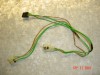
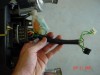
Now you're ready to start to start wiring
in the 48845 harness. The 48845 harness has a four wire side and a three
wire side. The four wire side will be wired in the to the "upstream"
portion of the bike's tail light/brake light harness and turn signal wires.
The three wire side sends voltage to the rear tail light/brake light bulbs.
I recommend using the more expensive butt connectors that are water proof.
They use heat shrink as well as glue. After crimping, hold a match or
other heat source is close to the connector and it will melt expelling a small
amount of glue that seals the connection. The wiring will be as follows:
FOUR WIRE SIDE
|
HARNESS
GREEN
= BIKE'S RIGHT SIGNAL +12V (GREEN
on mine but should be LIGHT BLUE)
|
|
HARNESS
RED = BIKE'S
GREEN WITH
YELLOW
STRIPE
|
|
HARNESS
YELLOW = BIKE'S
LEFT SIGNAL +12V (GREEN
on mine but should be ORANGE)
|
|
HARNESS
BROWN
= BIKE'S
BROWN
|
THREE WIRE SIDE
|
HARNESS
GREEN
= BIKE'S RIGHT TAIL BULB GREEN
|
|
HARNESS
YELLOW = BIKE'S
LEFT TAIL BULB GREEN
|
|
HARNESS
BROWN = BIKE'S
BROWN
|
|
TAIL BULB
GREEN
WITH YELLOW STRIPE
= BIKE'S GREEN
(for ground)
|
***Thanks to "Jay" aka "nineoneniner"
from the Yahoo Hornet's message board for the wire connections.
 Now
all you have to do is just plug the harness in. The
ORANGE connector on the harness goes to the
ORANGE connector on the bike. The
LIGHT BLUE connector on the harness goes to
the LIGHT BLUE connector on the bike.
The CLEAR
connector on the harness goes to the larger
CLEAR connector on
the bike. That's all there is to it. I used a zip tie to tidy up the
wires, and put some black corrugated wire wrap over the wiring to protect it.
I then slid the entire unit into the frame. Be sure to put the clear
wiring protector back over the plugs to protect them. Test everything out
to be sure it's working before buttoning up the bike.
Now
all you have to do is just plug the harness in. The
ORANGE connector on the harness goes to the
ORANGE connector on the bike. The
LIGHT BLUE connector on the harness goes to
the LIGHT BLUE connector on the bike.
The CLEAR
connector on the harness goes to the larger
CLEAR connector on
the bike. That's all there is to it. I used a zip tie to tidy up the
wires, and put some black corrugated wire wrap over the wiring to protect it.
I then slid the entire unit into the frame. Be sure to put the clear
wiring protector back over the plugs to protect them. Test everything out
to be sure it's working before buttoning up the bike.
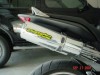
With the turn signals integrated into the
rear brake light, you can now trim the fender to a more sporty height. I
removed nearly all of the rear fender, leaving just enough to mount the license
plate. Currently on my bike the TBR exhaust cans are the lowest point in
the rear. I also flipped the license plate bracket upside down. This
make the license plate have a nice angle.
 To
trim the fender, I used a tape measure to measure off points along the fender
where I wanted to cut. I then connected the points with the ruler. I
then used a dremel tool with a cut off wheel to cut along the line I had drawn.
I then used 220 grit sand paper to clean up the edge, followed by 600 grit wet
dry sand paper, used dry. Finally, I drilled two 5/64th inch holes for the
license plate bracket bolts and mounted the bracket.
To
trim the fender, I used a tape measure to measure off points along the fender
where I wanted to cut. I then connected the points with the ruler. I
then used a dremel tool with a cut off wheel to cut along the line I had drawn.
I then used 220 grit sand paper to clean up the edge, followed by 600 grit wet
dry sand paper, used dry. Finally, I drilled two 5/64th inch holes for the
license plate bracket bolts and mounted the bracket.
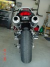 I'm
extremely happy with the results. When I turn the right turn signal on,
the right side brake lamp flashes, when I turn the left turn signal on the left
side brake lamp flashes. When the brakes are applied, they work as normal.
When a turn signal is activated and the brakes are applied the lamp indicating a
turn will flash fast and the other lamp will illuminate as a brake lamp.
The below pictures are ACTUAL representations of how this looks. The front
signals will match the rear signals, so when the brake is applied the front
signal will also flash faster. I find this a very nice feature as it will
be more likely to get other drivers' attention when you slow to make a turn.
I'm
extremely happy with the results. When I turn the right turn signal on,
the right side brake lamp flashes, when I turn the left turn signal on the left
side brake lamp flashes. When the brakes are applied, they work as normal.
When a turn signal is activated and the brakes are applied the lamp indicating a
turn will flash fast and the other lamp will illuminate as a brake lamp.
The below pictures are ACTUAL representations of how this looks. The front
signals will match the rear signals, so when the brake is applied the front
signal will also flash faster. I find this a very nice feature as it will
be more likely to get other drivers' attention when you slow to make a turn.
-Speedy919